Currently Empty: $0.00
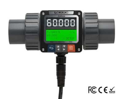
FP-AS510 patent AxleSense paddlewheel flowmeter
Applicable for
PCB wet process | Panel industry | Semiconductor | Water treatment | Food Manufacturing | Dyeing | Chemical industry | Waste water without large particle
Call or Email For Pricing
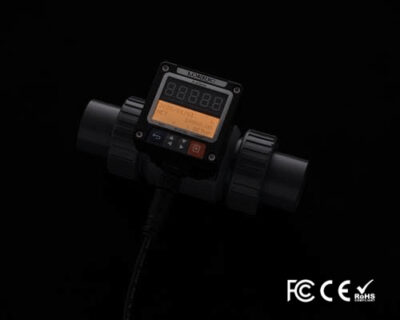
Made in Taiwan and featuring the patented AxleSense technology,
Inspected and proofed by SGS, RoHS compliant, the FP-AS510 has a measuring range that doubles that of other brands, which allows for the detection of any disappearance of the paddle which tends to cause zero-flow problems, on top of large indicator lights and a large screen that allows for more convenient on-site supervision.
Features
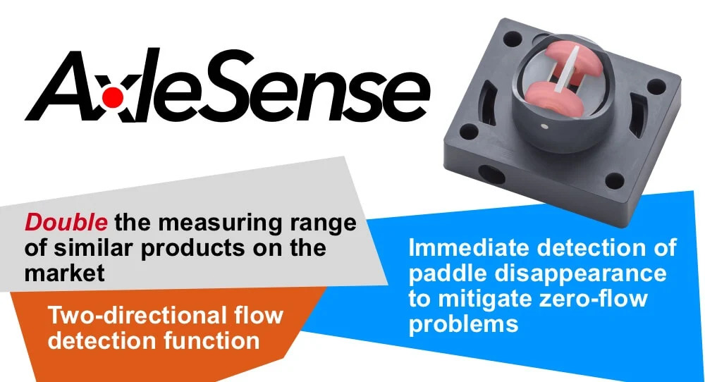
The Patented AxleSense Technology
Patent received technology – LORRIC improved upon the conventional design of placing the magnet on top of the paddle, creating a unique patented “AxleSense paddle”. On top of that, LORRIC redesigned the flow measurement algorithm, thus introducing the new patented “AxleSense” technology, which allows for a substantial upgrade in the sensing capabilities of extremely small flow rates, as well as the immediate monitoring of any paddle abnormalities.
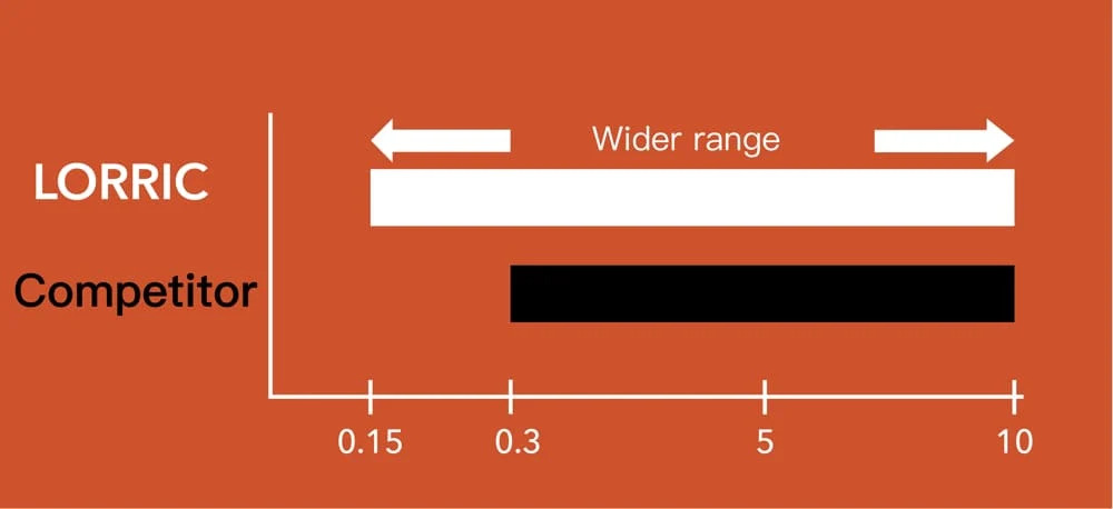
(0.15 m/s~10m/s)In traditional paddle wheel flowmeters, the sensing magnet is placed on top of the paddle, which means that during low liquid flow speed phases, flowrate detection has a large margin of error, even to the level of not being able to detect any flow at all. LORRIC’s paddlewheel flowmeter employs the patented AxleSense technology which shifts the direction of flowrate detection, which means that even under low flow speeds, any paddle movement will be accurately sensed, as well as maintaining a low margin of error for flowrate monitoring, which in turn provides the user with a more extensive application range.* The lowest flow rate may be slightly different due to factors such as piping diameter and fluid coefficient.
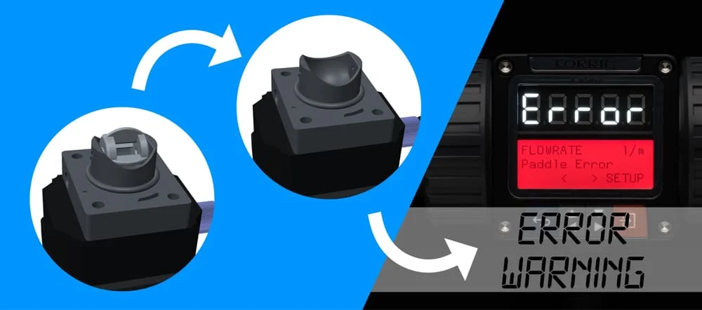
An active smart mechanism for the detection of flow problems that arise from paddle disappearance
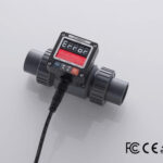
A flowmeter’s inability to detect flow may originate from problems in the pump, pipes, the equipment itself, or because of problems of crystallization, wear and tear or fracturing of the paddlewheel flowmeter that may cause the paddle to be damaged or fall off. LORRIC’s patented AxleSense technology actively detects any paddle abnormalities and offers clear information for the on-site manager to see, and will not simply display a passive “zero-flow” notice. Regarding industry 4.0 users, LORRIC’s paddlewheel flowmeter’s detailed information can be integrated with the factory’s management system, which helps on-site workers to solve any flow problems even faster.
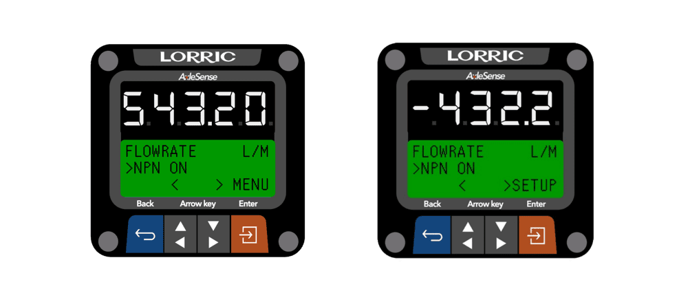
Bidirectional flow detection
LORRIC’s patented AxleSense technology uses the paddle’s direction to detect the flow’s fundamentals, while at the same time supplying direct information about the flow direction inside the pipelines. This in conjunction with integration with the factory’s management system, makes on-site management more convenient.
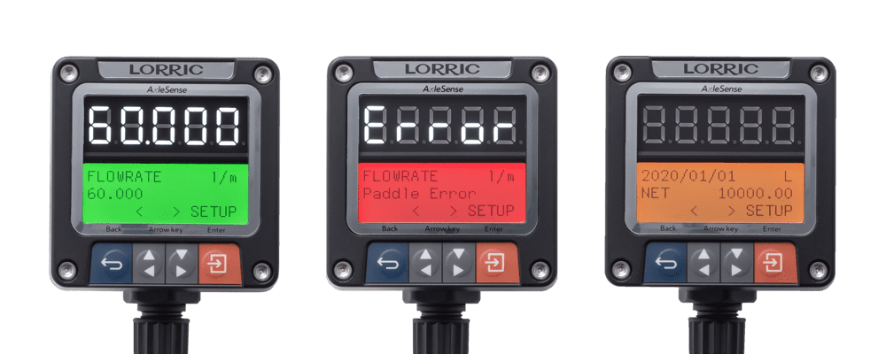
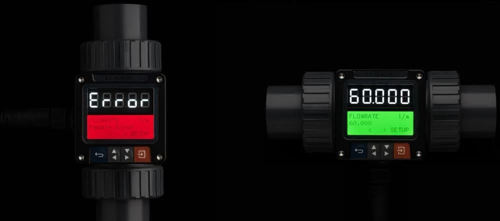
Large green, orange and red alarm indicator lights
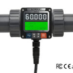
- Large bright LED screen allows for data monitoring at any time from far away, which saves the need to constantly check the screen from up close.
- Green, orange and red indicator lights: Red – Major abnormality; Green – Normal operation; Orange – Non-urgent data display. This system’s big advantage is that no matter how far the user stands from the screen, the changing indicator light’s color can clearly indicate the status of the equipment and whether any abnormality occurs.
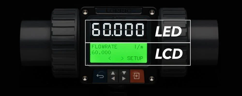
Exclusive LCD/LED double screen design, double screen monitoring
Currently in the process of filing for a patent trademark in the whole world
- Double screen display: LED-5 digits LED/LCD 16×3 LCD backlight display
- Large bright LED digits display screen for flow observation: LED’s brightness is best suited for long-distance monitoring. Because of limited display space – numbers are better suited than words. In LORRIC’s design philosophy, we chose to line up a large LED screen to display mostly numerical data for flow monitoring. This allows the users standing further away to clearly observe the immediate flow conditions without the need to get closer.
- LCD screen best suited for the display of more complex text-based details: Software interface, screen clarity, and button design all contribute to a superior more convenient installation experience, especially at times when attempting to use small narrow spaces for flowmeter installation. LORRIC’s paddlewheel flowmeter’s LCD screen can be used for the task of installation and setup, as the LCD screen’s ability to display more detailed text makes it easier for the user to clearly identify all needed options, thus contributing to smoother and quicker flowmeter installation process.
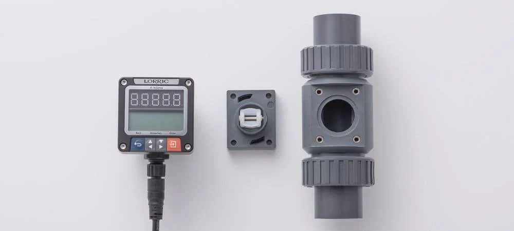
A three-pieces design tailored to conform mainstream market specifications
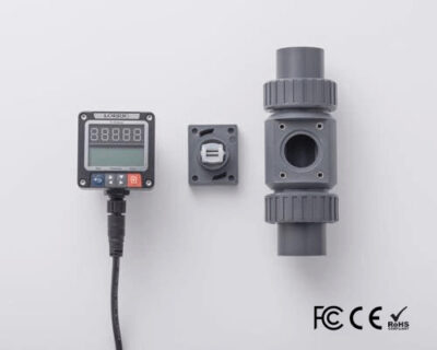
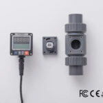
- LORRIC’s paddlewheel flowmeter’s three-pieces design of device, paddle set, and pipe, matches common market specifications. When wishing to replace the pipe, it is possible to replace the whole flowmeter set, allowing for more accurate flow detection, or in circumstances when the pipe cannot be replaced, it is possible to simply continue using the old one and save on the pipe replacement costs.
- The paddlewheel’s paddle can be replaced on its own.
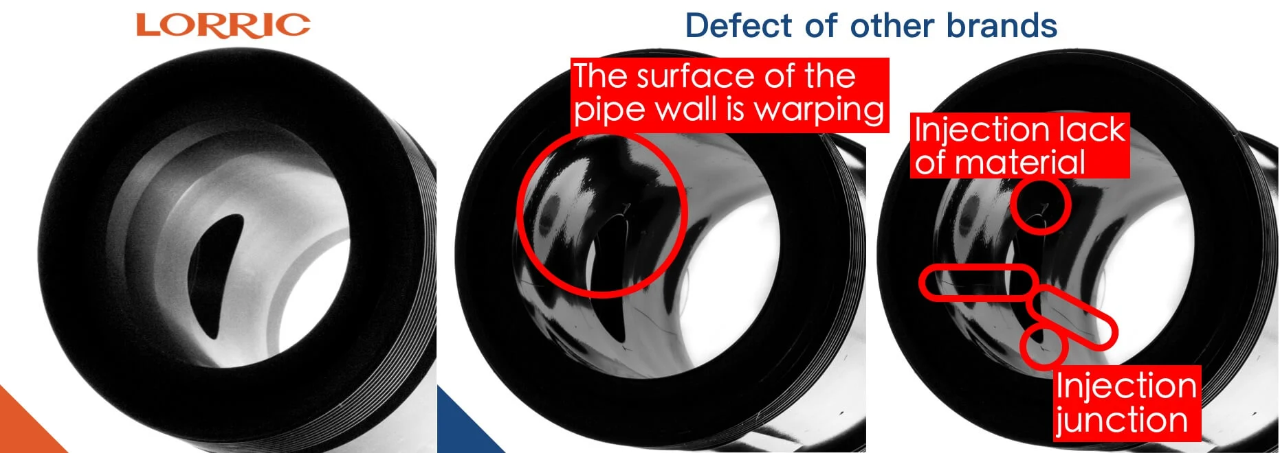
LORRIC’s machined T-connector pipe is made sturdy and durable. The pipe’s interior wall has stable dimensions, no warping and no leakage. It has a complete and seamless surface.
LORRIC’s T-connector pipe:
- Our machining process turns an extruded plastic bar into a delicately machined durable T-connector pipe.
- The pipe’s size is stable and reliable.
- The pipe wall is smooth and not warped. (This reduces turbulence and produces higher accuracy.)
- The plastic injected by turning has higher strength than the injection product, and there is no encapsulation, short shot, and bonding line.
Other brands’ T-connector pipe:
- The average T-connector pipe is made by plastic injection molding.
- The thicker the part, the greater the shrinkage, causing the surface of the pipe’s wall to be uneven and wavy (see the middle T-connector photo). This leads to inconsistent cross-sectional areas of the pipe and turbulent fluid, which further affects the calculation results and is prone to leakage.
- In addition, the common encapsulation, short shots, and inevitable bonding lines of injection products are structural weaknesses (see the middle T-connector photo), and they are easily damaged from these positions with long-term use.
Other important properties
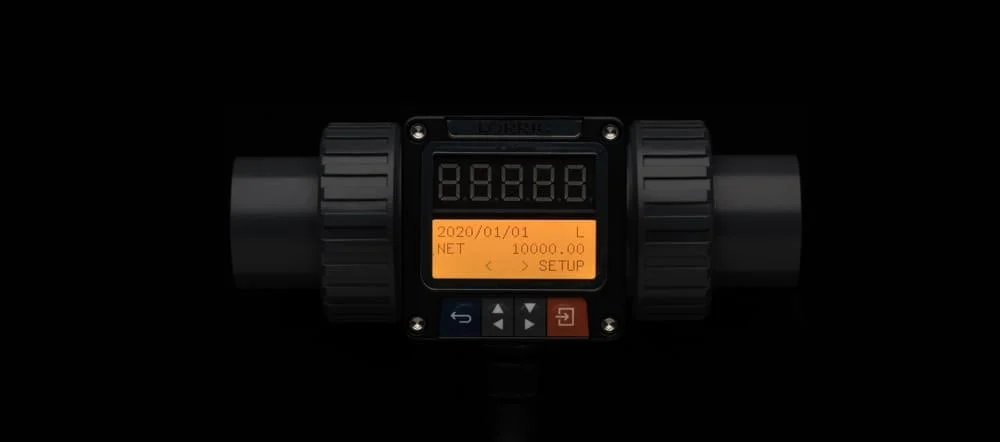
Daily accumulation of positive/negative/net flow volume for the past 14 daysWhen concerning basic non-manufacturing facilities, generally speaking, no PLC system monitoring should be undertaken – LORRIC’s paddlewheel flowmeter provides accumulated monitored data regarding several kinds of flow: Positive flow volume, negative flow volume and net flow volume. You have the option to set one of these to have 14 days’ worth of its data stored (up to 10 numeral digits can be displayed simultaneously). At the same time, thanks to the added extra battery, even in cases of power outage, data and dates will still be kept in order.
The screen can change direction according to the pipes’ alignmentWhether your pipes are horizontal or vertical, LORRIC’s paddlewheel flowmeter’s header, screen and display panel can all be adjusted according to the pipes’ direction, making for convenient flow monitoring under different circumstances.
| Variable area flowmeter | Paddle wheel flowmeters | LORRIC’s Paddle wheel flowmeter |
Electromagnetic flowmeter | Ultrasonic flowmeters | |
| Pipeline loss | Low | Low | Low | No | No |
| Non-invasive install | No | No | No | No | Yes |
| Precision | Middle | Middle | Middle | High | High |
| Bidirectional flow detectable | No | No | Yes | Yes | Yes |
| Blockages | Possible | Possible | Possible | Not possible | Not possible |
| Applicable fluid | Air / Liquid | Liquid | Liquid | Conductive liquid | Liquid |
| Cost | Lowest-costs in small diameter pipe, cost increases with pipe diameter | Low-costs, cost increases with pipe diameter |
Low-costs, cost increases with pipe diameter |
High-costs, cost increases with pipe diameter | Middle-costs Cost does not increase with pipe diameter |
| Mechanism Specs | Measurement Specs | User Interface | |||
| Installation method | in-line (Pipe segment) | Applicable fluid maximum dynamic viscosity | 300cSt ** | Language | English, Traditional Chinese, Simplified Chinese (Others customizable) |
|
Fluid in pipes temperature
|
UPVC:0~50 °C (32~122°F), For higher temperature, please use PPH or PVDF or 316L Stainless Steel* |
Applicable fluid | Clear, oil or chemicals with less impurities (<1%) | Unit |
Metric:Litre, cubic meters, meters Time:second, minute, hour, day Imperial:foot, Cubic foot, Uk gallon, US gallon |
| Device working environment temperature | -10~60°C
(14~140°F) |
Linearity | ± 0.5 % FS (>0.3m/s) | ||
| T-connector adapter | UPVC Gluing adapter(ASTM, JIS, DIN), UPVC internal and external thread adapter (BSPT and NPT),PPH / PVDF insertion welding fitting, UPVC / PPH / PVDF Spigot (See order example below for details) |
Reproducibility | ± 0.4 % | Display | Double screen display :Large 5-Digit LED,
16×3 3-Color Backlight LCD display |
| OR tolerance | ± 2.5 % OR | ||||
| T-connector diameter | DN15-65 (½” to 2-1/2″) | Measuring principle | Paddle Wheel | Display digits | LCD 5 Digits (4 digits when negative value)LCD 10 Digits (Not including sign and decimal point) |
| Paddle material | PVDF or PPH with embedded magnet + ceramic bearing and shaff | Flow velocity range | ± 0.3~10m/s Can extend to ± 0.15m ~ 10m/s *** | ||
| T-connector material | UPVC / PPH / PVDF (Made to order)/ 316L Stainless Steel | Operation button | 4 Key touch buttons | ||
| Power supply | DC 12V to 36V 100mA | Transient data | Instantaneous flow velocity and flow volume | Wired communication |
Self-powered Analog output 16bit 4-20mA (Device after HW1.3) Modbus RTU RS485 Two-line OCT switch signal (ship with 2 meter cable) |
| Response time | < 0.5 or 1 second | Cumulative data |
Positive and negative net flow volume accumulation, past 14 days and long time accumulative net flow volume |
||
| Waterproof level | IP66 * | Calendar function battery | CR2032 | ||
* IP66: The IP Code, International Protection Marking, IEC standard 60529, sometimes interpreted as Ingress Protection Marking, classifies and rates the degree of protection provided by mechanical casings and electrical enclosures against intrusion, dust, accidental contact, and water. The first digit indicates the level of protection that the enclosure provides against access to hazardous parts (e.g., electrical conductors, moving parts) and the ingress of solid foreign objects.The second digit indicates the level of protection that the enclosure provides against harmful ingress of water.
First 6 stands for dust tight: No ingress of dust; complete protection against contact (dust tight). A vacuum must be applied. Test duration of up to 8 hours based on air flow.
Second 6 stands for powerful water jets: Water projected in powerful jets (12.5 mm) against the enclosure from any direction shall have no harmful effects.
** The device is calibrated with normal temperature water. Fluids with different viscosities may have different results, and may also change the minimum and maximum flow velocity.
**The flow velocity range may be slightly different due to factors such as piping diameter and fluid coefficient.

| UPVC pipe – union diameter size(mm) | ||||||||
| A | B | C | D | E | F | G | H | |
| ½” | 164 | 100 | 27.6 | 36 | 62.3 | 46.2 | 115.7 | 86.2 |
| ¾” | 168 | 100 | 32.6 | 41.9 | 62.3 | 50.5 | 115.7 | 85.7 |
| 1″ | 168 | 100 | 40.6 | 50 | 62.3 | 60 | 115.7 | 85.7 |
| 1¼” | 210 | 114 | 50.2 | 59.6 | 65 | 75.6 | 127 | 89.2 |
| 1½” | 218 | 120 | 56 | 65.7 | 70 | 83 | 134 | 92.5 |
| 2″ | 269.5 | 133.3 | 72 | 81 | 81 | 99.7 | 148.8 | 99 |

| UPVC pipe – spigot pipe diameter size(mm) | ||||||
| A | B | C | D | E | F | |
| 2½” | 160 | 70 | 76 | 92 | 106.5 | 152.5 |

| Device size(mm) | |
| I | J |
| 63 | 63 |




There are no reviews yet.